I talk about network topology maps and network planning here
Creating a network topology map using Ciscco Packet Tracer
Setting up a small network of a few network and end devices using Hubs/Switches. It includes configuring LAN Cards, interfaces, preparation of cables, assigning IP addresses, and checking the connection of the network, all done in Cisco Packet Tracer, a network topology mapper.
We will be using Cisco Packet Tracer to create a network topology map for the given example network
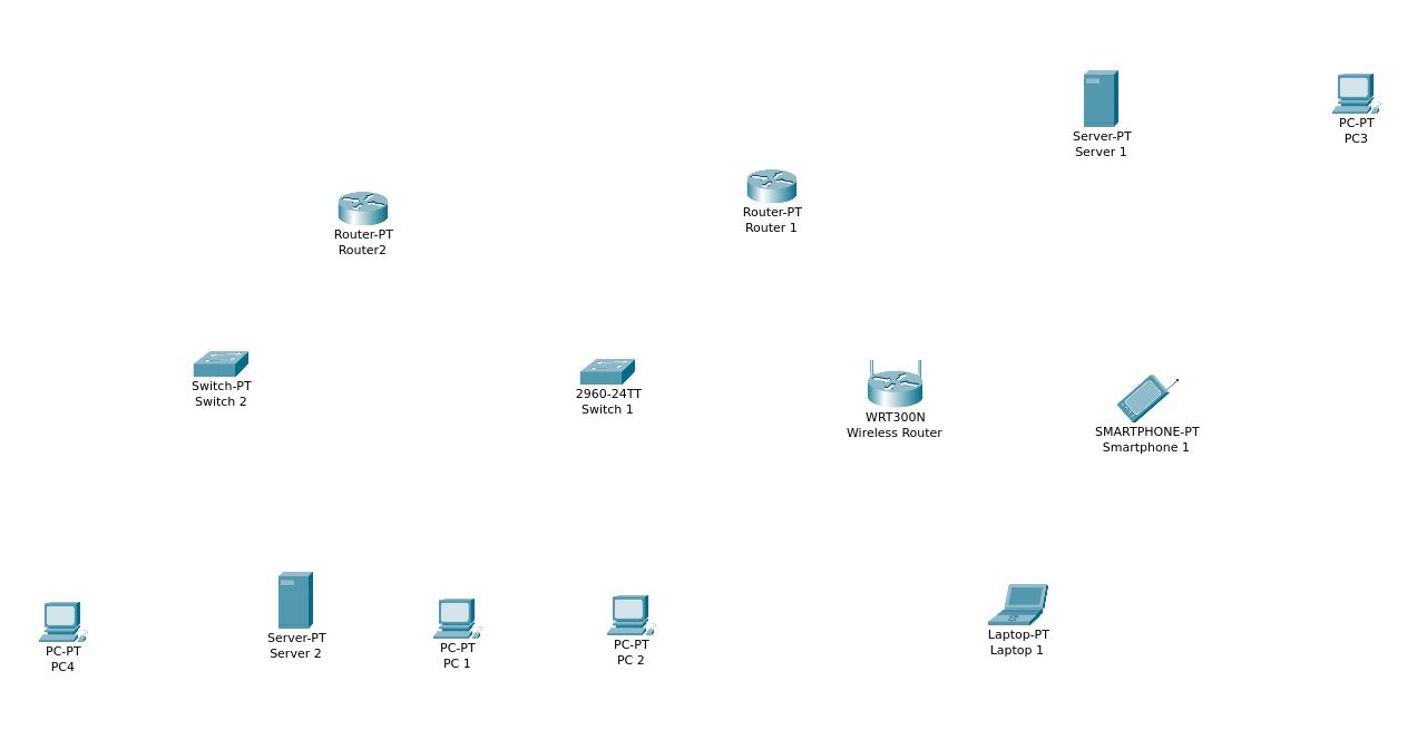
Open up Packet Tracer and go to the Logical view, and start adding devices.
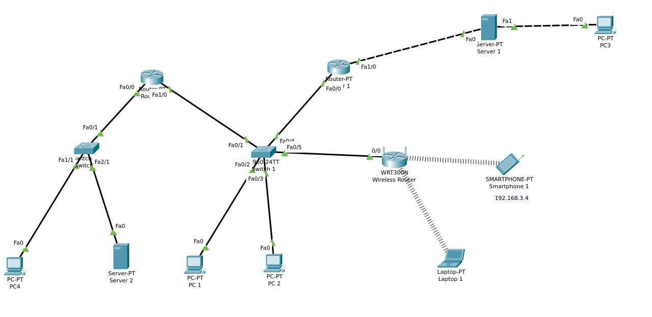
After all the network and end devices have been added, begin adding connections. You can add or remove network interfaces to these devices and create connections.
You can start to configure all the devices individually
Configuration of all devices
We must design an IPv4 addressing plan, having
- unique IPv4 addresses for interfaces of every system
- a network mask
We will be using this IANA reserved block of IPv4 addresses for use on this private network-
IPv4 address range 192.168.0.0 - 192.168.255.255
netmask 192.168.0.0
To connect to the network, a system must have at least one physical network interface
When adding a second network interface to a host like this, this interface must also have its own unique IP address
We will be dividing all the devices and systems into three sub-networks, interconnected by three routers. Subnetting is very useful for larger networks to prevent problems with broadcast storms. In this case, it is mainly for having a logical and easy to remember schema
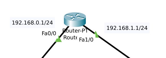
It is also a good idea to add a note listing the assigned (static) IP addresses, by the side of the devices. Here, I will be using CIDR notation to denote router IPv4 addresses
When constructing the network topology map, remember to change the names of devices to reflect the source map
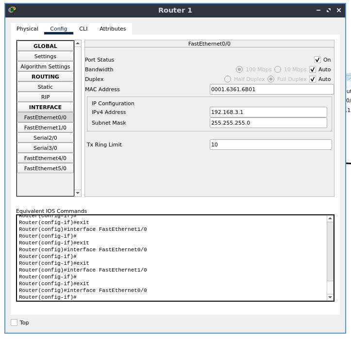
Router 1
Enable the ports you need to use. Disable all the rest of the ports as a security measure.
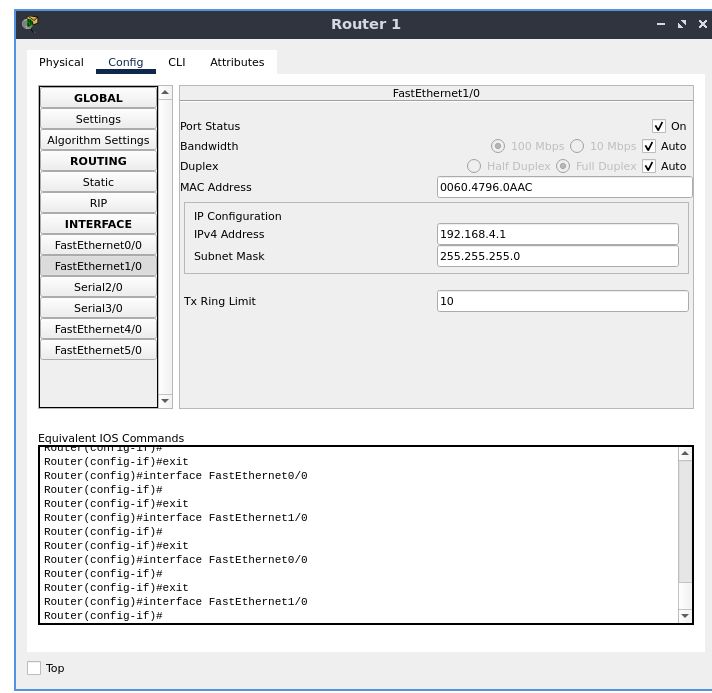
Double click the router device to configure it. Go to the “Config” tab. Under the “GLOBAL” section, select “Settings” to change the device’s name in the network map. The interfaces will be listed under “INTERFACE”. Select the first interface FastEthernet0, the /0 suffix is the port number. Here, each FE interface has a single port. For each port being used, configure an IPv4 address and subnet mask.
Here,
FastEthernet0/0 -> 192.168.3.1
FastEthernet1/0 -> 192.168.4.1
subnet mask for both -> 255.255.255.0
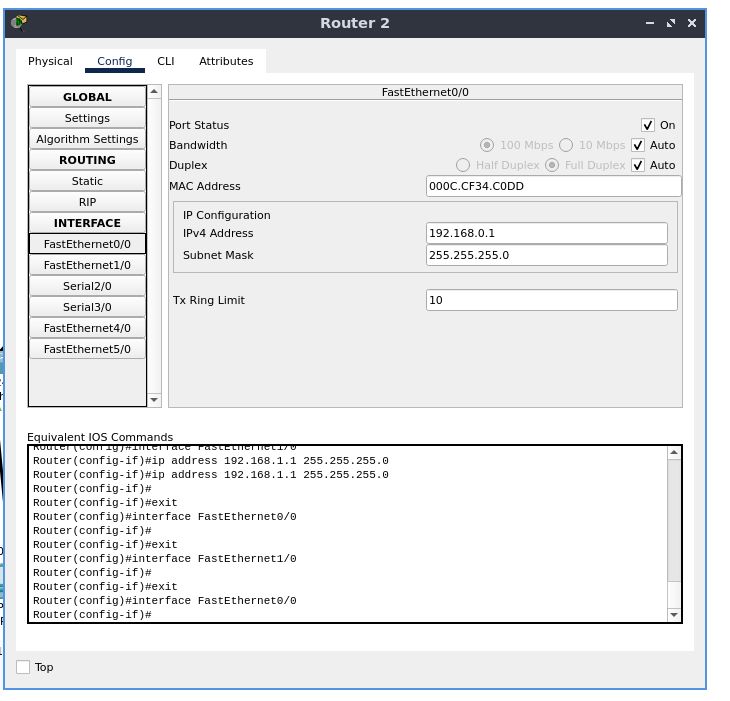
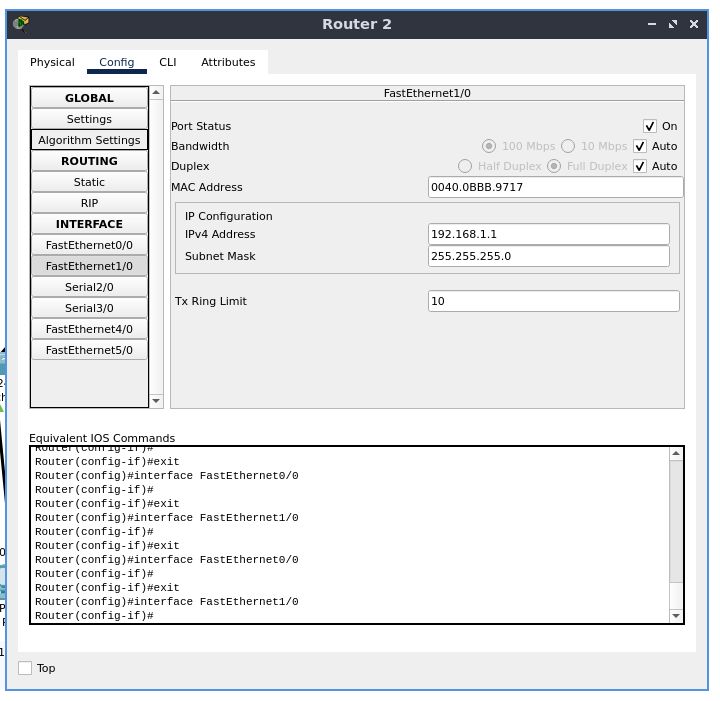
Router 2
Similarly, configure the second router
Remember-
The start address eg. 10.0.0.1 is always reserved for the router.
Do not assign an address that ends in .0 or .255, these are reserved for network protocols
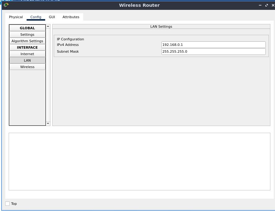
Wireless Router
Go to the LAN configuration and configure the IP address and subnet mask
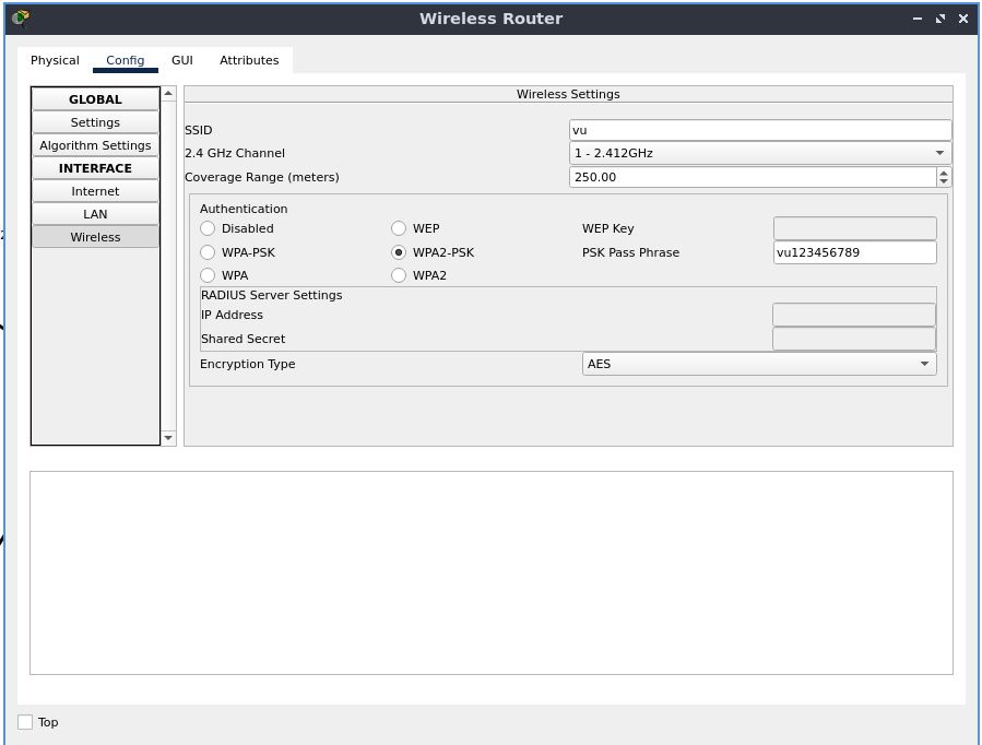
To configure wireless settings-
set an SSID- here, “vu”
this router is a single band (2.4GHz) router, you can configure the channel if you’d like to
For authentication, use WPA2-PSK(do not use WPA, WEP as they are outdated and insecure), and enter the pre-shared key (PSK) to the side
here, “vu123456789”
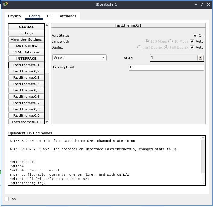
Switch 1
Enable ports that you will be using. Make sure the rest of the ports are disabled
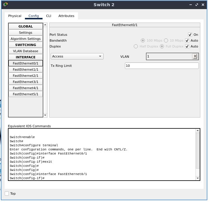
Switch 2
Set up in a similar fashion
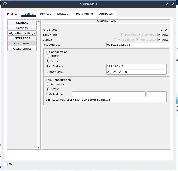
Server 1
As we have started configuring IPv4 for end devices, keep in mind the IP address pool, and addresses you must not use
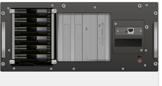
This server has only one NIC, so we must power the machine down and add another one in the empty slot
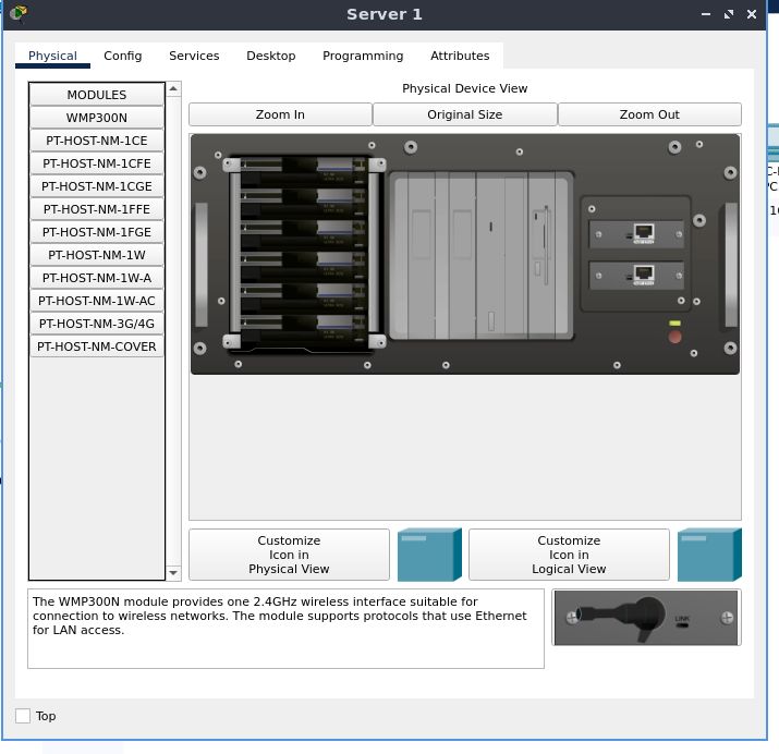
As stated in the beginning, we must allocate two unique IP addresses for these two interfaces, after powering on the machine.
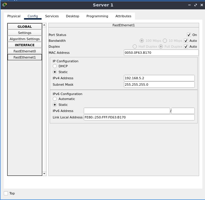
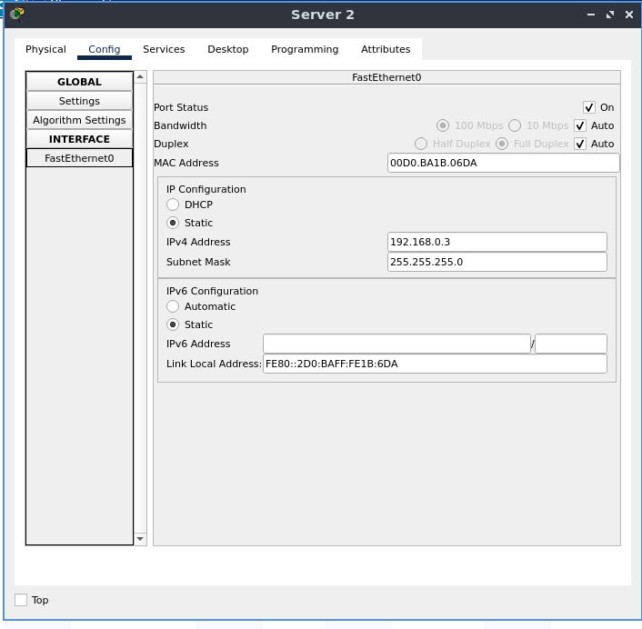
Server 2
Set this up in accordance with the source topology map, in a similar fashion
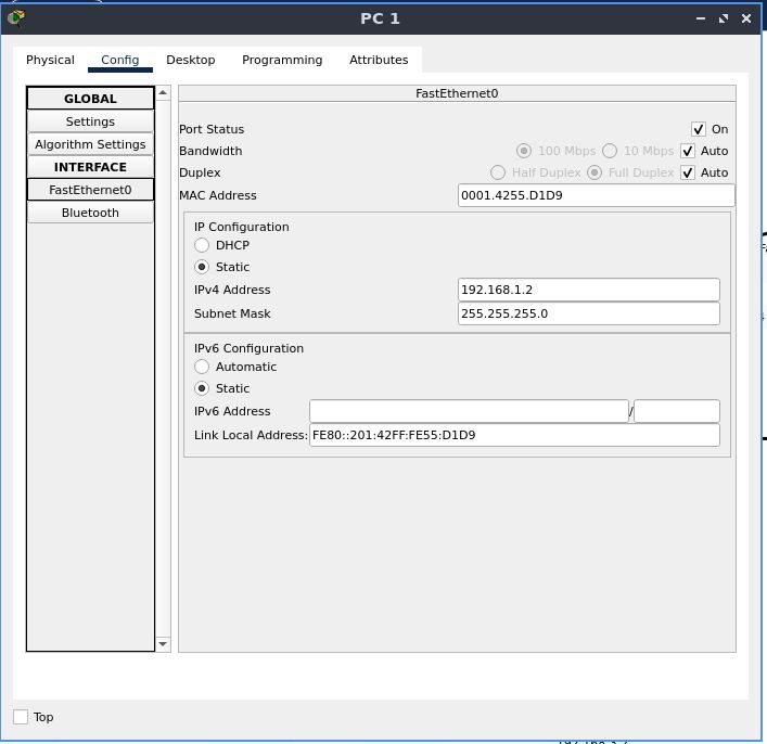
PC 1
Set the IPv4 default gateway manually to “192.168.1.1”. Also statically configure the IPv4 address and subnet mask like we’ve done before
PC 2
set the default gateway address by looking at the addressing scheme and subnetting

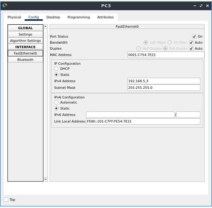
PC 3
set this host up in the same way
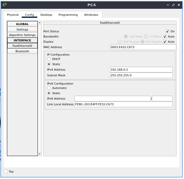
PC 4
set this host up in the same way
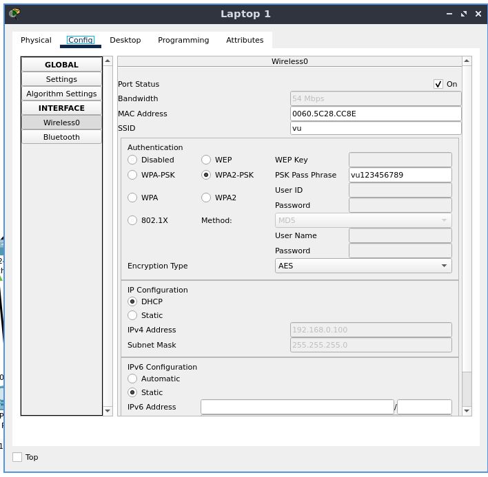
Laptop 1
add a wireless NIC if not already present. Authenticate to the wireless router, with the PSK(SSID is given above)
Set up the gateway manually or use DHCP
For convenience sake, you can use DHCP to configure hosts connected wirelessly
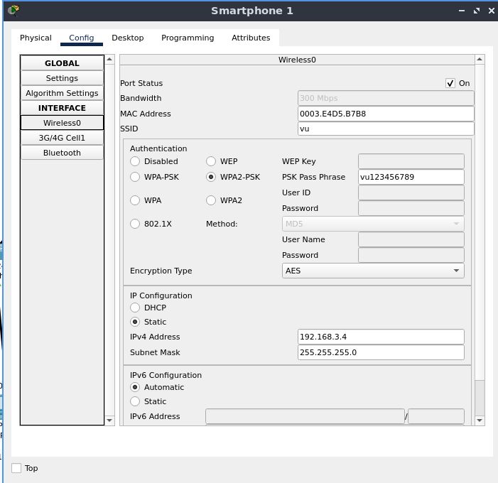
Smartphone 1
For convenience sake, you can use DHCP to configure hosts connected wirelessly
Here, it is configured a static IP address 192.168.3.4
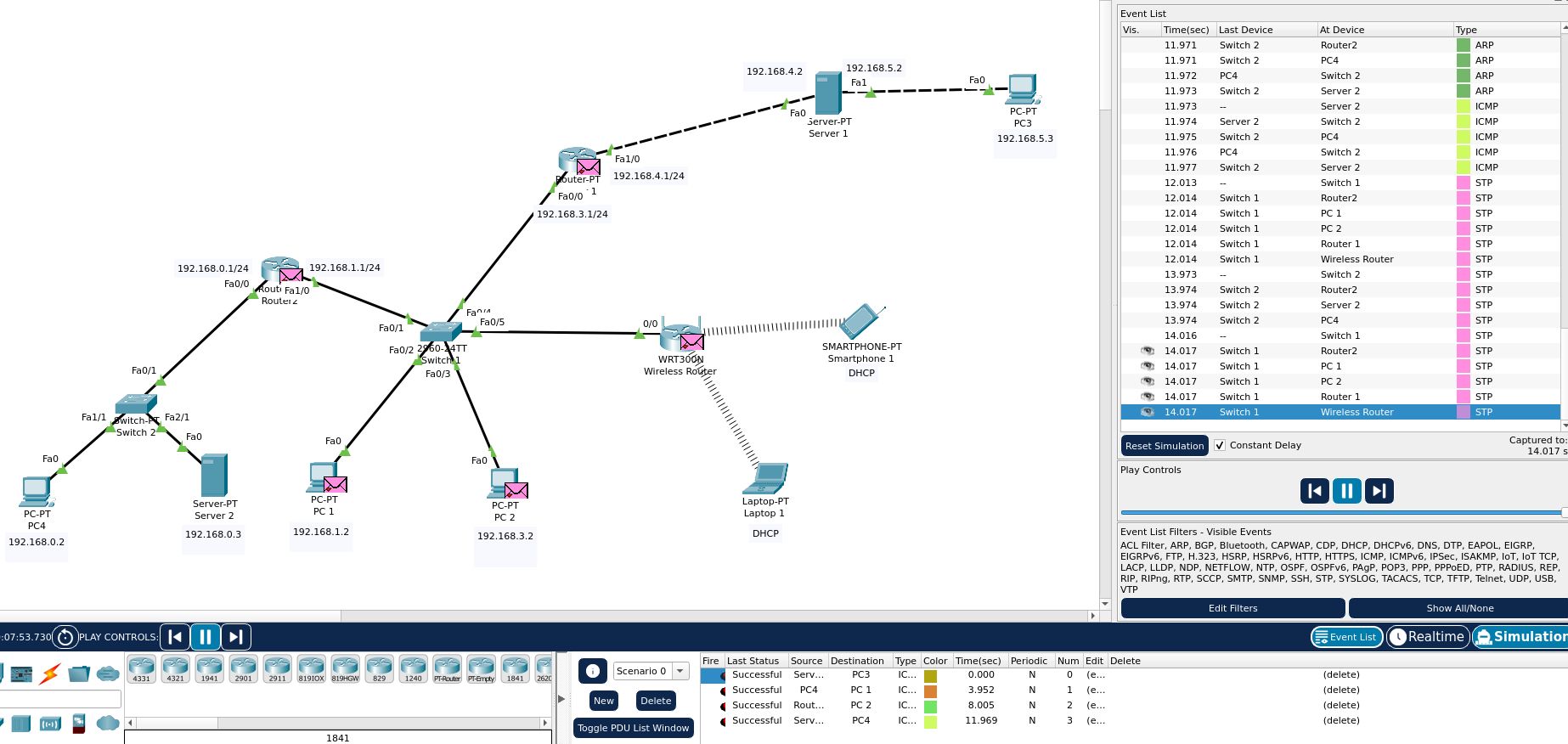
Testing Connectivity
After making a few more modifications, this is our final topology map:
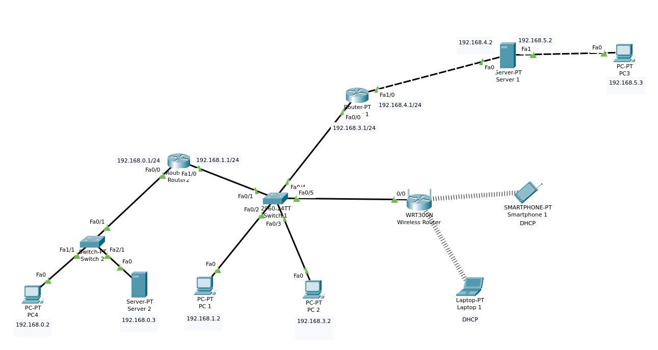
We now go to the simulation tab and try to use error-reporting protocols that network devices can use to generate error messages to the source IP
We will use this as a tool to verify network connectivity. Make sure all the tests listed at the bottom are marked with “successful”. Run the simulation at a preferred speed to see the simulated network, including your tests, along with other STP, DTP, ARP, etc. traffic flow.